

Wiring loom
| Pin | Functie | Kleur/subkleur | Bijzonderheden |
|---|---|---|---|
| 1 | 5Volt | Blue-Red | Supply MAP / TPS |
| 2 | Lambda | Purple-White | Analog 0-5V input |
| 3 | Coolant Temperature | Yellow | Thermistor input |
| 4 | Air Temperature | Orange | Thermistor input |
| 5 | Digital input PE0 | Purple-Green | Switch to GROUND |
| 6 | Crank signal + | Afgeschermd Grey | Crankshaft sensor |
| 7 | Cam signal + | Afgeschermd Blue | CAM phase sensor |
| 8 | CAN_L | Green | CANbus signal low |
| 9 | 12V Supply | Red-Green | Fuse 2A |
| 10 | Ground | Black | Ground on engine block |
| 11 | Massa | Zwart | Ground on engine block |
| 12 | Stepper 1B | Grey-Black | Max 1A |
| 13 | Stepper 2B | Grey-Blue | Max 1A |
| 14 | Ignition A | White | Pulse Ignition Coil. Max 60mA |
| 15 | Progr.output LED15 | Pink | Switching to ground Max 5A |
| 16 | Progr.output JS11 | Brown | Switching to ground Max 5A |
| 17 | FuelPump relay | Purple | Switching to ground Max 5A |
| 18 | PWM F-idle valve | Darkgreen-Brown | Switching to ground Max 5A |
| 19 | Injection Ch1 | Green-White | Switching to ground Max 5A |
| 20 | Injection Ch2 | Green-Pink | Switching to ground Max 5A |
| 21 | Analog input JS5 | Dark-Green | Analog input 0-5V |
| 22 | Analog input JS4 | Blue | Analog input 0-5V |
| 23 | Throttle Position | Blue-White | Analog input 0-5V |
| 24 | MAP Sensor | Blue-Yellow | Analog input 0-5V |
| 25 | Digital input PE1 | Purple-Grey | Switch to ground |
| 26 | Crank signal - | Shielded Grey | HALL requires 1V Pull-up |
| 27 | Cam sensor - | Shielded Grey | HALL requires 1V Pull-up |
| 28 | CAN_H | Yellow | CANbus signal low |
| 29 | SensorGround | Black | Ground for sensors |
| 30 | SensorGround | Black | Ground for sensors |
| 31 | Ground | Black | Ground to engine block |
| 32 | Stepper 1A | Grey-Red | Max 1A (12V@power-up) |
| 33 | Stepper 2A | Grey-Yellow | Max 1A (12V@power-up) |
| 34 | Ignition B | Grey | Pulse Ignition Coil. Max 60mA |
| 35 | Ignition C | Pink | Pulse Ignition Coil. Max 60mA |
| 36 | Ignition D | Brown | Pulse Ignition Coil. Max 60mA |
| 37 | Ignition E | Dark-Green | Pulse Ignition Coil. Max 60mA |
| 38 | Ignition F | Blue | Pulse Ignition Coil. Max 60mA |
| 39 | Injection Ch3 | Green-Purple | Switching to ground Max 5A |
| 40 | Injection Ch4 | Green-Black | Switching to ground Max 5A |
Power supply and safety circuit
At least 2 relays are used for the EFIgnition cable harnesses.
Main Relay
Fuel pump Relay
The main ralay / main relay prevents a voltage drop over the original wiring or components such as ignition switch.
The Fuel Pump Relay or fuel pump relay prevents the presence of voltage on components such as fuel pump, injectors, ignition coils and other actuators when the engine is not running.
We usually place other relays close to the consumer, such as close to a ventialtor.
The diagram looks like this:
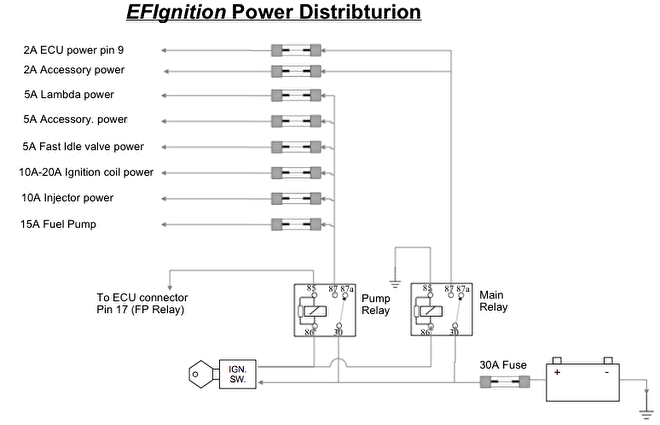
The relays are powered by the battery. The ignition lock gives the relay voltage coil. The main relay switches on immediately when the key switch is turned. The fuel pump relay is operated by the EFIgnition and only comes on when necessary.
A typical behavior is that the fuel pump relay switches on for a few seconds when the ignition is switched on and then falls off. When starting, the EFIgnition recognizes a speed and the relay will switch on again.
Each group is separately secured. A fuse close to the battery prevents the cable harness from breaking if there is a short circuit somewhere between the battery and the fuse box.
Sensors CLT IAT TPS MAP
The following sensors are all fairly easy to connect. There are a few points for attention.
- The thermistor sensors (temperature sensors) are not allowed to make mass anywhere, except on the sensor mass of the EFIgnition.
- The TPS sensor can be connected incorrectly so that it works incorrectly or it becomes an adjustable short circuit.
- The MAP sensor will break if it is not connected correctly.
- There are not enough sensor ground pins on the ECU. These may / must therefore be shared among several sensors.
- There is one 5V output for several sensors. So you must / may also split this.

Crankshaft and Camshaft sensor
VR sensor
Connecting an inductive or VR sensor is easy. Provide a shielded cable. The shield may only be grounded at the ECU. There are 2 wires in the disconnected cable which come at the plus and minus of the sensor.
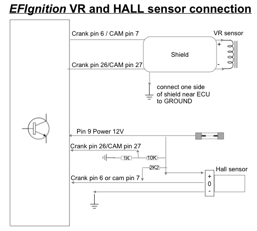
A HALL sensor or Opto sensor is a bit more difficult in terms of connection. There is a piece of electronics in the sensor. This electronics needs power to work. As a power supply we can use the same wire that supplies the EFIgnition with voltage. The mass of the sensor is made at the central mass point of the ECU.
Most of these sensors switch to ground. While the EFIgnition expects a voltage. A pull-up resistor is then required. This is the 2k2 Ohm (2200 Ohm) resistor in the diagram. We need to raise the negative sensor circuit connection of the EFIgnition a bit so that the signal really goes through a threshold voltage when the sensor switches. We do this by making a voltage divider of 10k and 1k and offering the intermediate voltage to the negative connection of the sensor circuit.
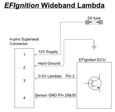
Connect the Lambda controller
The lambda controller ensures that the lambda probe is heated precisely to 750 degrees. It also converts the current signal from the lambda probe to a 0-5 Volt signal to be understood by the ECU.
The connection differs per lambda controller.
The 14Point7 Spartan2, for example, has 6 wires. The Innovate Motorsports LC-2 has 4.
Not all wires will be connected (NC).
| Function | 4-pin Superseal | LC-2 | Spartan2 |
| 12V | Pin 1 Purple-Red | Red | Rood |
| Ground | Pin 2 Black | Black | White |
| 0-5V | Pin 3 Purple-White | Yellow | Green |
| SensorGround | Pin 4 Purple-Black | NC | Black |
| NB output | NC | Brown | Brown |
| SensorStatus | NC | NC | Blue |
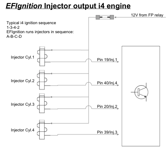
Connecting the injectors
Impedance
Pay attention to which injectors you use. The EFIgnition circuits are only suitable for high-impedance injectors. Measure the resistance of the injectors. This must be at least 10 Ohm.
Connection four-cylinder
The EFIgnition has a "Low Side" circuit. This means that the injector is switched to ground. The EFIgnition runs the injector channels in order. So make sure that the correct injector is on the correct channel. See also the diagram below.
Connection 6/8/12 cylinder
The EFIgnition has 4 final stages for the injection. To control a 6 cylinder we use only 3 and we connect 2 injectors parallel to each channel. The engine is now running semi-sequentially. We can do the same with a V8 engine. But now we use the 4th injection channel. With a V12 we use 3 groups and we connect 4 injectors to each group.

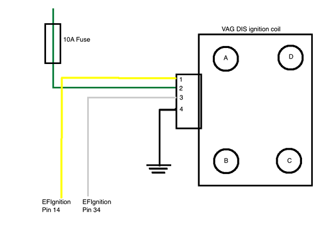
Connecting the ignition coil(s)
EFIgniton output sends out a pulse. Therefore, ignition coils with a built-in ignition transistor must be used, or an ignition module must be added.
The connection of, for example, a VAG DIS ignition coil is as follows:
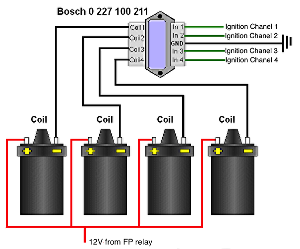
If we use ignition coils without a built-in ignition transistor, we must install an ignition module. The connection then looks like this:
V8 / V12 engines
The EFIgnition has 6 ignition coil channels. However, we do not all have to use these. A 4 cylinder connected to a DIS coil uses only 2 coil channels. The remaining channels can be used for other functions. With a V8 that runs on a DIS coil, only 4 coil channels are used. We can also run a V8 on 8 individual ignition coils. We then let 2 ignition coils spark at the same time. We call this "wasted spark". For example, it is possible to run a V12 with 12 separate ignition coils. If the V12 has 2 spark plugs per cylinder, then we can work with 12 DIS ignition coils, so that 1 coil causes 2 spark plugs to spark.
Connect idle control
Stepper motor
The EFIgnition has a stepper motor driver. The stepper motor consists of 2 coil pairs that allow the motor to take small steps by switching the coils on and off, but also by reversing the flow direction. There are 2 channels. Each channel has 2 wires. These belong together. If wire 1A plus 12V, wire 1B is ground. If the ECU switches then wire 1A becomes ground and wire 1B plus 12V.

The control is fairly precise. If the connection is incorrect, a coil will get 2x plus or 2x minus, so the motor will not work properly.

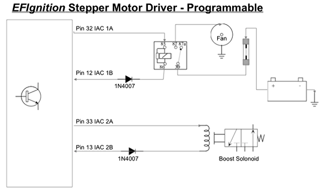
If we do not use a stepper motor but a PWM F-idle valve (or no stationary control at all) then we can use the IAC outputs to control something. For example a Boost-control solonoid or an E-Fan control.
The current may be a maximum of 1A.
At rest there is voltage on this circuit. So there will be a current if we connect something to it. The pairs 1A, 1B and 2A, 2B belong together and may not be exchanged. The moment the function becomes active, the flow direction will reverse. To prevent that the relay, the actuator or the lamp always stays on, we must include a diode in the circuit (1N4007).
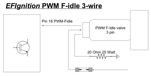
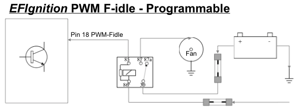
PWM F-Idle Valve
This valve works with Pulse Width Modulation. There are roughly 2 variants:
- 2 wires
- 3 wires
The wiring goes about the same, except that a resistor of 20 Ohm must be added for the 3-wire. Note: this must be a resistor that can disipate at least 25Watt of heat.
Some 2-wire PWM F-idle valves contain a diode. It is particularly important to have the polarity correct for these valves. Test this before connecting the valve. Wrong connection will cause a short circuit and possibly damage the ECU.

If no PWM F-idle valve is applied then this port can be freely assigned. Then you can connect this circuit as below and, for example, connect a relay for a fan to it.
Analogue inputs
Various accessories can be connected to the analog 0-5V input. Such as a pressure sensor (fuel pressure, oil pressure or barosensor), a potentiometer, a knock module or an EGT module. We have connected a potentiometer in the diagram below. Please note: if ignition outputs E and F are in use, the analogue inputs are occupied and nothing may be connected to them.
