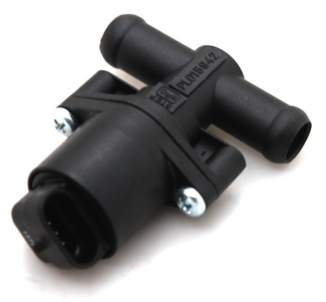
Steppermotor Idle control valve (IACV)
The EFIgnition also supports a stepper motor. The stepper motor literally works with steps and is therefore very precise. It is slightly more difficult to adjust properly, but after that the result is better.

There are four wires on the EFIgnition that can control the stepper motor. They work in pairs. Wire pair 1A and 1B provide the current for coil 1. Wire pair 2A and 2B provide the current for coil 2.
It is an interesting circuit. At rest, a voltage of 12 volts comes from wires 1A and 2A. Dr wires 1B and 2B are ground. If a step has to be taken, it turns around, 1B and 2B now become 12 volts and 1A and 2A now become ground. Channels 1 and 2 can switch independently of each other. This creates magnetism in the engine over and over at a different location, which opens or closes the valve step by step.
Freely programmable - use a diode (1N4007)
If we do not use a stepper motor, then these 2 channels are available to do something else. For example, to switch a relay for a cooling engine. The wires 1A and 1B then belong together. 1A then comes to terminal 85 of the relay, terminal 1B now comes to terminal 86 of the relay. Connection 30 goes via a fuse to the battery plus. Connection 87 goes to the cooling motor.
But it doesn't work yet. Because electricity will flow through the relay coil. After all, 1A has 12 volts, 1B gives mass. The relay will switch. If the function is active there will be 1A mass and 1B 12 volts. The relay remains switched on. A relay in series with these wires with the barrier in the direction of wire 1A prevents this. The relay is now not switched on in the normal state. If the function becomes active, current can flow from wire 1B to the relay, through the diode to wire 1A.
Make sure you use the correct relay. This may not contain a diode.

