Crank position sensor
We want to measure the crankshaft position as precisely as possible. We do this with the help of a sensor, the crankshaft sensor. This is usually a VR sensor. Let's take a look at a trigger wheel. We position the sensor at 0.5 to 1.5 mm from the trigger wheel. Normally perpendicular to the teeth. In the example below, the sensor is perpendicular to the teeth. This is quite a rare setup and I would nor reccomend it this way. But it would work.
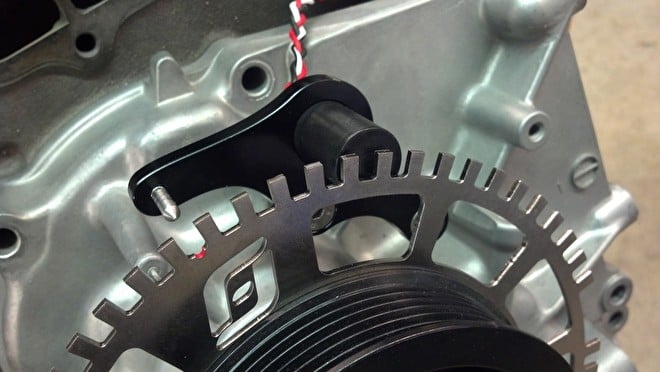
Triggerwheel met HALL sensor in haakse opstelling
Trigger wheel
The trigger wheel consists of an iron wheel. Do not take aluminum or stainless steel. The sensor does not respond to this. The trigger wheel has a series of teeth of which 1 or 2 are missing. For example 36 teeth, one of which is missing. We are talking about a 36-1 trigger wheel.
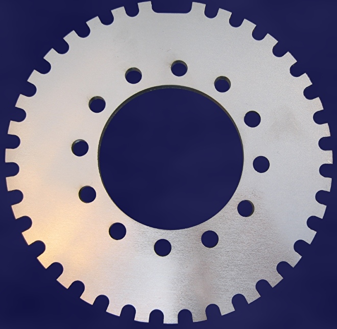
36-1 Triggerwheel
By now defining the missing tooth in the system, the ECU knows when there has been a whole lap and what the angle of the missing tooth is with respect to the Upper Dead Point (TDC) of cylinder 1. Ideally we place the missing tooth of the trigger wheel where no spark will have to be given. The ECU will work less precisely in the missing tooth area. For a four-cylinder engine, an angle of 60-120 degrees is therefore excellent. Note: First comes the missing tooth, 60-120 degrees later comes cylinder 1 on TDC.

De triggerhweel instellingen
The ECU can calculate the crank angle from the missing tooth. With a 36-1 trigger wheel, we have a tooth every 10 degrees. However, if we now want to make a spark at 25 degrees before the BDP, the ECU will not see a tooth at that time. She then calculates where the BDP is located by measuring the elapsed time from the last tooth. The more teeth on the trigger wheel, the more precisely it runs. The most commonly used standards are: 60-2, 36-1, 36-2 and 12-1. It is important that the number of teeth must be divisible by the number of cylinders and that it is an even number. A 5 cylinder is therefore best run on a 60-2 trigger wheel. If we have a motorcycle that runs 15,000 rpm, you can better reduce the number of teeth. Otherwise the sensor will no longer read the teeth properly. A commonly used standard for motorcycles is 12-1.
The trigger wheel is decoded
This means that every tooth of the trigger wheel is counted. If the ECU counts an incomplete number (or too many) of teeth, the process is interrupted. The engine will then "hitch". This is a very annoying behavior. But it points you to an error. The ECU indicates it as a "sync loss". By interrupting the process, the ECU ensures that ignition does not occur at an incorrect time. There are many systems that mask a "sync loss". With these systems, the inflammation may be 10 or more degrees earlier than intended. This can cause engine damage. Decoding the crankshaft angle is therefore very important. It ensures a very precise ignition time and gives a very clear signal when there is a fault in the crankshaft signal.
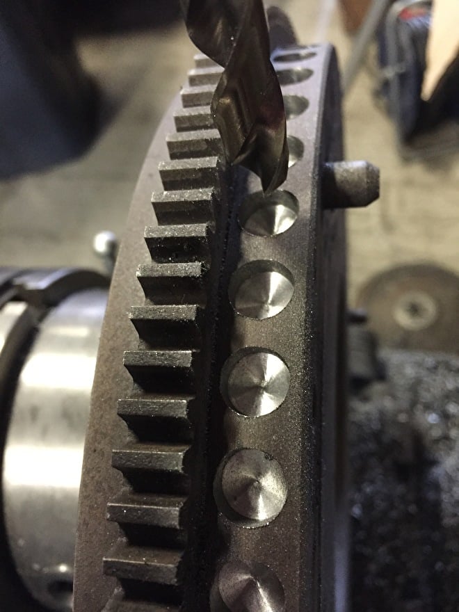
Triggerwheel alternatives
On some engines there is no crankshaft pulley on which we can attach a trigger wheel. Measuring on the camshaft is a bad idea. The camshaft turns but half the crankshaft speed and the ignition time will be less precise. What remains is an adaptation to the flywheel. We can also drill holes instead of teeth. The sensor reads the same. So now, for example, we are drilling 58 holes at 6 degrees apart. We do not drill 2 teeth. The sensor reads the wheel exactly the other way around, but we can adjust that by changing the sensor polarity.