

Engine speed sensor
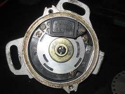
The engine speed sensor is the most important sensor of the engine management system. In addition to the speed, this sensor, together with the trigger wheel determines the crankshaft position.
In addition to a crankshaft position sensor, a camshaft phase sensor can also be used.
The sensors are available in 3 variants.
- The Variable Reluctance sensor
- The HALL effect sensor
- The OPTO sensor
The VR sensor
This sensor consists of a magnet around which a coil is wound. By moving a piece of metal towards the sensor, the magnetic field will change. The same happens when we pull the metal away from the sensor. The changing magnetic field in the coil of the sensor will generate a voltage. If the metal object moves towards it, the voltage will be positive, if the metal object moves away from it, the voltage will be negative. The signal coming from the sensor is therefore a varying positive and negative voltage. An alternating voltage. We see a new sinus for every tooth of the trigger wheel.
The voltage generated by this sensor differs. At starting speed this will be approximately 1 Volt (measured in the AC position). This can be as high as 100 volts if the engine makes a lot of revs.
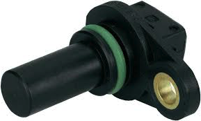
VR sensor
The HALL effect sensor
Responds to magnetism. This sensor has its own magnet, but also a piece of electronics that responds to the proximity of a magnet. In the case of a HALL sensor with built-in magnet, the metal of the trigger wheel ensures that the magnetism reaches the sensor. Most HALL sensors will switch to ground if there is metal nearby. This signal is interrupted if there is no metal nearby. The sensor therefore produces no sine wave and the voltage cannot be measured. A "pull-up" resistor is required to make a switching signal.
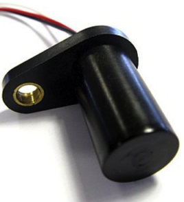
HALL sensor
VR or HALL sensor
We usually use a VR sensor as a crankshaft sensor. As a camshaft phase sensor we usually use a HALL sensor. We can sometimes see the difference between those sensors, but you can defenetly measure it.
A HALL sensor ALWAYS has 3 connections. Namely a power supply (+), a mass (-) and a signal (0).
A VR sensor sometimes has 2 connections and if it is a type with a wire it usually has 3 connections. You can measure the coil between 2 connections. This will give a resistance of between 150 and 1200 ohms. You do not measure anything on the third thread. This is the shielding of the wire. The shield ensures that no interference can occur in the signal due to influences from other wiring. With the ECU, this shield must be grounded. We measure much higher resistance values with a HALL sensor.
OPTO sensor
This is a light lock sensor. This is found in some Japanese cars. For example in the Mitsubishi 4G63 system, used in the first Mazda MX-5, among others. In terms of connection in identification, it behaves the same as the HALL sensor.
OPTO sensor