

MAP sensor
The pressure in the manifold is measured with the Manifold Absolute Pressure (MAP) sensor. By looking at the density of the air in the manifold, you can determine how much air is now entering the engine. This is not the same for all engine speeds, because the shape of the intake, exhaust and the camshaft profile also plays a role. A motor therefore has a corresponding degree of filling for every pressure and speed.
We call this Volumetric Efficiency.
Injection
The amount of air entering the engine must now be mixed with the correct amount of gasoline. This can be recorded in the VE index. The VE index indicates the degree of filling of the engine and controls how long the injector is open.
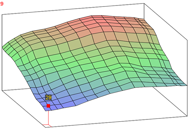
VE table for fuel metering
Ignition timing
The correct moment of ignition of this mixture also depends on the cylinder filling.
The burning speed depends on the final compression pressure. When the gas valve is almost closed, there is a high engine vacuum. There is then a low final compression pressure. The flame front will slowly spread over the combustion chamber after ignition. It takes more time before the peak pressure is reached. The inflammation must now be relatively early.
If the gas valve is open far, the motor vacuum is low. A lot of air is drawn in and the final compression pressure is high. As a result, combustion will take place quickly and peak pressure will occur quickly. The ignition must now be abandoned otherwise the peak pressure will occur too early and the engine will detonate.
The firing moment depends on the speed and final compression pressure. We can record the ignition moment in a similar field of ignition.
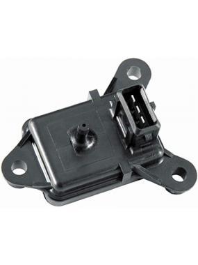
Types of MAP sensors
There are many different forms of MAP sensors. Roughly there are 2 forms:
External MAP sensors
MAP sensors that are built into the manifold.
The extene MAP sensor is connected to a vaccine hose. There are a number of important guidelines:
The MAP pipeline must be as short as possible. Then the MAP sensor responds faster.
The MAP pipe must be connected to the central pipe of the manifold, preferably not near the gas valve and never directly opposite an inlet pipe to the cylinder head.
The MAP sensor must be able to drain. So the connection should preferably point downwards.
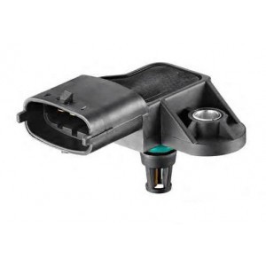
The internal MAP sensor will have its connection directly to the intake manifold. The seal is provided by a rubber or O-ring. Sometimes these sensors also have a built-in air temperature sensor.
The operating pressure of the MAP sensor
The pressure of the MAP sensor has been chosen by the manufacturer to give an optimal resolution. The MAP sensor is powered by 5 volts. She gains mass and has an output on it that gives a voltage of 0-5Volt. The height of the voltage indicates the pressure. But there are sensors that have a working pressure of 5-105 Kpa and there are sensors that have a working pressure of 25-400 Kpa. We can record the working pressure of the sensor in the EFIgnition software. It is wise to select a sensor that matches the motor. For example, you do not mount a MAP sensor on a turbless motor that can measure up to 500 Kpa. Because then it only works in a voltage range of 0-1 Volts. The indication is then less precise than if we were to use a sensor that would go up to 105Kpa. The correct sensor works almost over the full 0-5 volts.